Instruction Flow
Lamlet
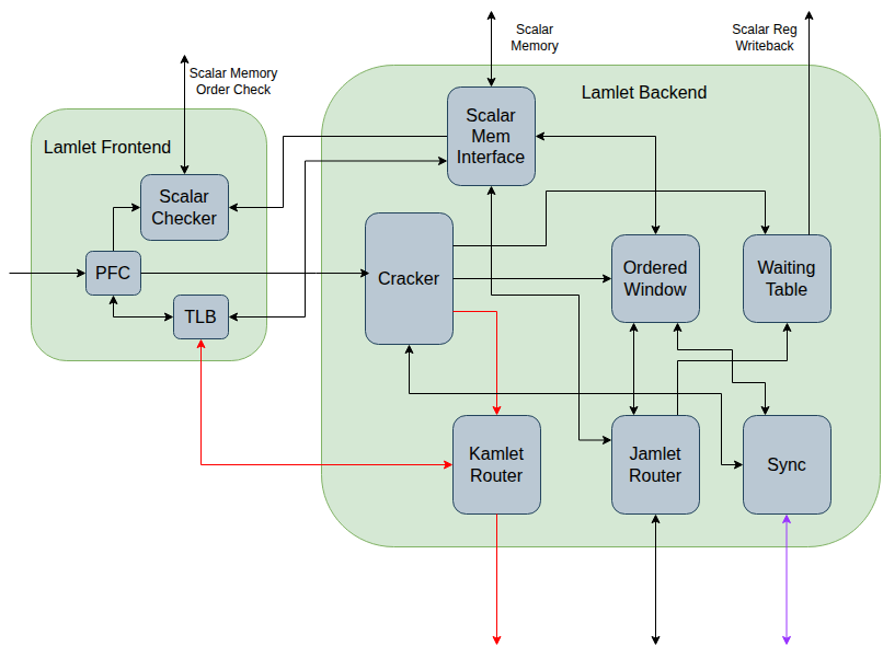
1) The decoded RISC-V vector instruction enters the lamlet frontend from the host processor.
2) It enters a Pipeline Fault Checker (PFC) which determines which pages the instruction will access. It informs the Scalar Checker if it accesses any scalar memory pages, so that it can prevent memory clashes with the scalar processor. If the PFC determines that there are no page faults then the vector instruction is delivered to the lamlet backend. If page faults are found then that is handled by the processor. If the PFC cannot determine whether or not there is a page fault, then the instruction is passed to the lamlet backend but the further processing in the lamlet frontend is stalled until the backend can determine whether or not there was a fault.
3) In the lamlet back end the vector instruction is processed by the Cracker. This splits the RISC-V vector instruction into a sequence of kamlet instructions (kinstructions). Splitting is done based on cache line accesses (there is a preference for each kinstruction only accessing one cache line) and to convert a complex instruction into a sequence of simpler kinstructions (e.g. reduction instructions are broken down into several data movement and arithmetic kinstructions). The Cracker also knows the EW configuration for each vector register, and will insert EW remapping operations where required. During the cracking, additional temporary vector registers may be required. There are a total of 48 logical registers, 32 of which map to the RISC-V architectural registers, and 16 of which are available as temporary regs to the Cracker. The produced kinstructions are either broadcast to the kamlet mesh over the kamlet network, or they are sent to the Ordered Window module. Some kinstructions require later actions by the lamlet. These are also sent to the Waiting Table where the necessary state is stored. For example some kinstructions will return values to the lamlet over the synchronization network or the jamlet network, and state required to process these responses is stored in the Waiting Table.
5) If the kinstruction is sent to the Ordered Window module, then this module will initiate a series of interactions directly with the jamlets to process the operations in the correct order. This is described in Ordered Window.
Kamlet
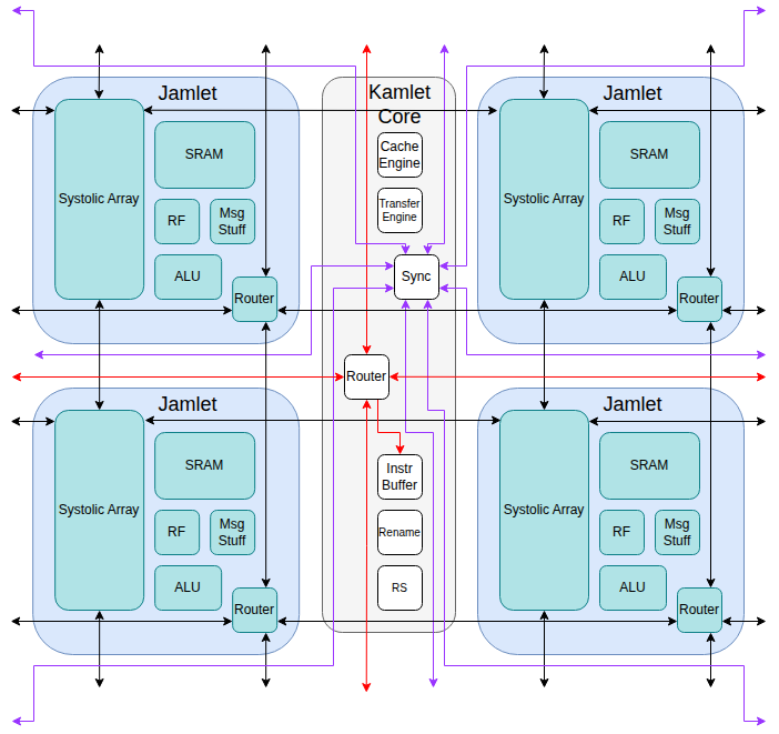
6) KInstructions arriving at the kamlet are placed into the Instruction Buffer (probably 64 kinstructions depth).
7) When there is space available in the Reservation Station, kinstructions are popped from the Instruction Buffer and the registers are renamed and mapped to the 48 physical registers. There are 48 logical registers and 48 physical registers, however 16 of the logical registers are only used for temporary variables and are explicitly freed when not in use. After the registers have been renamed the kinstruction is placed in the Reservation Station.
8) The Reservation Station tracks which physical registers, cache lines and resources (e.g divider hardware) each kinstruction requires. Each cycle it issues the oldest kinstruction that is ready to execute. KInstructions are divided into 'Local Kinstructions' and 'Non-Local Kinstructions', depending on whether they require any out-of-lane communication. 'Local Kinstructions' are issued directly to the jamlets which immediately execute them with deterministic latency. 'Non-Local Kinstructions' are placed in the Kamlet Transfer Engine as well as having state in each of the *Jamlet Transfer Engines.
9) The Transfer Requester, Transfer Server and Transfer Receiver in the jamlets work with the data from the jamlet and kamlet transfer engines to communicate with other jamlets by sending and receiving messages over the jamlet network. The Synchronization Network is also used to synchronize between the kamlets when necessary. This is mainly to determine that the operation has completed on all kamlets and then the kinstruction can be removed from the Transfer Engines and the locks on the vector registers and memory released.